

How To Become a CNC Machine Operator
What is a CNC operator, and how does it differ from a CNC machinist? Find answers to this question here.
If you’re familiar with the CNC industry, you may have heard the term “geometric dimensioning and tolerancing,” commonly referred to as GD&T.
But what is GD&T, exactly?
This language of symbols is essential for CNC machinists to understand, as it helps engineers and designers communicate how to bring a part design to life. In the CNC world, detail is everything. So, processes like this are critical to creating parts efficiently and accurately.
GD&T can seem intimidating at first, but once learned, makes the life of a CNC machinist much easier. Follow along as we walk through a brief look into the history of GD&T, the basics of what it is, how it works and how it’s used in the industry.
Before jumping into exactly what GD&T is, it’s helpful to understand its history. During World War II, a machinist named Stanley Parker created the first GD&T concepts while he was working at a torpedo factory in Scotland. The origin of GD&T is credited to Parker, who created the well-known concept of "true position."
Parker worked at the Royal Torpedo Factory in Alexandria, West Dunbartonshire, Scotland. While employed there, his work significantly increased the production of naval weapons by new contractors.
In 1940, Parker published notes on “Design and Inspection of Mass Production Engineering Work,” which is the earliest work on geometric dimensioning and tolerancing. He published “Drawings and Dimensions” in 1956, which became the basic reference in the field.
After encountering a situation where torpedo parts did not meet inspection criteria, yet were actually functional parts, Parker started questioning traditional tolerancing techniques. He dug deeper and found that two-point tolerances result in a square-shaped zone of acceptability, and parts can still function if the tolerance zone is expanded into a circle that includes the corners of the square.
His idea developed into a complete organized system of controls and a global standard by 1957. Today, GD&T has four core elements: size, location, form and orientation. These provide a basis for 14 primary feature control symbols such as perpendicularity, circularity, parallelism and circular runout.
Read: Ferrous vs. Nonferrous Materials in CNC Machining
GD&T is a system for specifying and communicating engineering tolerances and design intent. It aids engineers and manufacturers in optimally controlling variations in manufacturing processes.
GD&T uses a symbolic language on engineering drawings and computer-generated, three-dimensional solid models. Essentially, “geometrical product specifications” are related to the size, shape and positional relationship of a product and “tolerance” refers to the allowable error.
“Geometric tolerance” includes the size and allowable errors for the form and position. GD&T answers the question, “How far off the CAD/perfect model can a part be and still function?” It also:
Read: How to Use a CNC Machine - 7 Effective Tips
Why are geometric tolerances used? Engineering drawings show the geometric dimensions for all features of a part. By the dimensions, a tolerance value must be specified with the maximum and minimum acceptable limit. The difference between the minimum and maximum limit is known as the tolerance.
For instance, if there was a table that would be acceptable with a height between 640 mm and 670 mm, 30 mm would be the tolerance.
However, the tolerance for the table communicates that a table that is 640 mm high on one side and 670 mm on the other or has a waved surface with 30 mm variation, is acceptable. To appropriately tolerance the product, a symbol is needed to communicate the design intent of a flat-top surface. As a result, in addition to the overall height tolerance, a flatness tolerance must be included.
In a similar way, a cylinder with a toleranced diameter will not fit into its hole if it becomes bent during the manufacturing process. So, it also needs a straightness control, which is tricky to communicate with basic plus-minus tolerancing. Parts with complex shapes and unpredictable variations require GD&T practices that go beyond basic plus-minus tolerancing.
Material condition modifiers (MCM) specify how a feature's allowable variation is affected by the part's actual size. These modifiers include:
By using these modifiers, designers and engineers can more accurately describe the functional intent of parts, ensuring a higher level of interchangeability and reliability in assembly.
Feature control frames (FCF) provide a standardized method to communicate complex geometric tolerances on engineering drawings. An FCF is composed of several compartments that collectively define how much a feature can deviate from perfect form. The key components include:
Using FCFs, manufacturing and inspection processes can achieve precise control over part geometry, ensuring parts meet their design specifications and function as intended in their final assembly.
Read: Introduction to CNC Milling
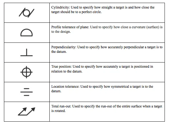
GD&T uses a library of symbols to communicate design intents. There are several standards available worldwide that describe the symbols and define the rules used in GD&T, including the American Society of Mechanical Engineers Y14.5 and standards from the International Organization for Standardization (ISO), which vary slightly.
The Y14.5 standard provides a complete set of standards for GD&T in one document. On the other hand, ISO standards typically only address one topic at a time. There are separate standards that provide the details for each of the major GD&T symbols. The geometric dimensioning chart below displays a handful of these symbols and what they mean.
Read: Safety Tips for CNC Machinists
GD&T is a large and complex topic, and diving into it is like learning a new language. It is a means of eliminating misinterpretation and is essential to machining, as it makes it easier to create acceptable mating parts.
“Essential to machining” and “easier to create acceptable mating parts” means that GD&T provides everything needed to ensure a part is manufactured to reflect feature relationships and ensure that mating parts will truly mate across thousands of parts and assemblies.
The drawing is the controlling document that ensures the vendor is creating precisely what the customer's design requires. When dealing with very small tolerances, such as +/- .002", it becomes even more important to use GD&T. If you have a cylinder that needs to be "cylindrical" within .0003", for example, you learn to use it very quickly.
One of the most significant benefits of GD&T is that it describes the design intent rather than the resulting geometry. Similar to a formula or vector, it is not the actual object—but rather, a representation of it.
When used correctly, GD&T allows statistical process control, which helps to reduce assembly failures and the means needed for quality control. This saves organizations substantial resources. Thanks to GD&T, multiple departments can work simultaneously, as they have a shared language and vision for what they want to create.
Read: CNC Machining vs. Manual Machining
So how does one learn to use geometric dimensioning and tolerancing in a CNC environment?
As mentioned previously, GD&T is very complex. This means that it often requires the completion of a formal training program, like Universal Technical Institute’s CNC Machining Technology program, to learn.2,85
Created in conjunction with Roush Yates, a leading brand in the performance industry, this 36-week program will teach you everything from reading blueprints and interpreting geometric dimensioning and tolerancing to the programming, setup and operation of CNC lathes and mills. UTI’s CNC program covers GD&T extensively in the CNC Basics course.
Throughout your training, you’ll have the chance to train with some of the same tools and technology used by machinists in the field today. This program combines classroom learning with hands-on application to prepare graduates to pursue a career in the field.
The CNC program is offered at UTI’s NASCAR Technical Institute campus in Mooresville, North Carolina. For students who need to relocate to complete their training, we offer housing assistance to help them find living arrangements near campus. Scholarships and grants may also be available to help eligible students lower the cost of their education.10
Read: What Is CNC Machining? 6 Most Common CNC Machines
GD&T stands for “geometric dimensioning and tolerancing.” It is a system that allows engineers to communicate allowable geometric variations precisely and unambiguously for parts and assemblies.
In engineering and manufacturing, GD&T is used to ensure that parts fit together as intended, function properly and can be produced consistently and cost-effectively. It helps in reducing the need for guesswork and interpretation, leading to higher-quality products and lower production costs.
Some commonly used GD&T symbols include the flatness symbol, which specifies the permissible variation in the flatness of a surface, and the circularity symbol, indicating how close a feature must be to a true circle. Other symbols like the positional tolerance symbol are used to control the location and sometimes orientation of features.
Read: CNC Machining Frequently Asked Questions
Does a career in the CNC industry sound like the right fit for you? Want a more in-depth answer to the question, “What is GD&T?”
UTI’s CNC Machining Technology training program begins frequently throughout the year, so you’re able to start training, dive deeper into geometric dimensioning and tolerancing, and prepare to pursue a career sooner! To learn more, visit our CNC program page to request information or call 1-800-834-7308 to get in touch with an Admissions Representative today.
Universal Technical Institute of Illinois, Inc. is approved by the Division of Private Business and Vocational Schools of the Illinois Board of Higher Education.